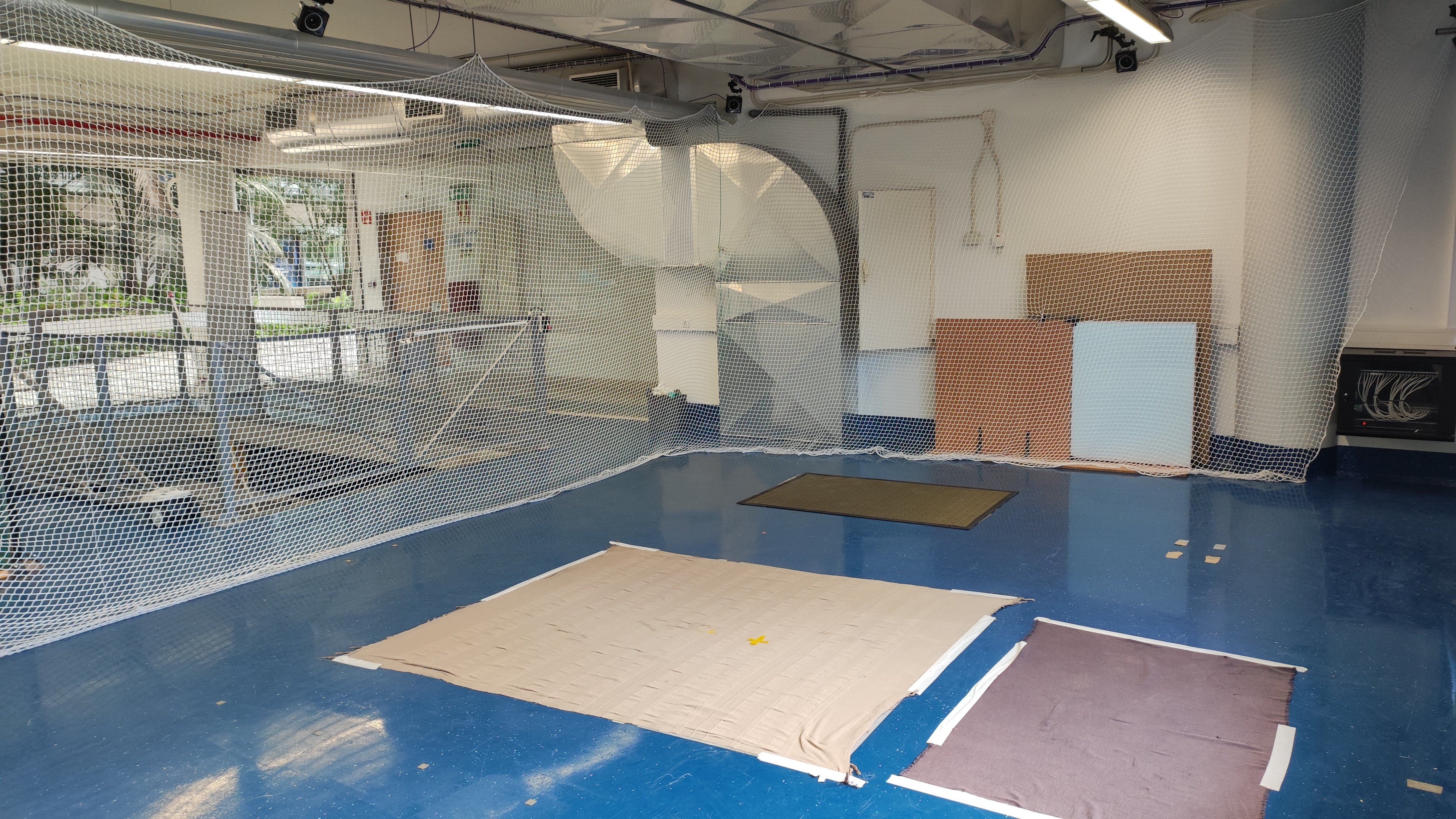
Taguspark Flight Arena
The Taguspark flight arena is an indoor space, under the administration of the ISR-Lisbon, which features an OptiTrack Motion Capture System (MCS). The MCS consists of 8 cameras that are mounted on the ceiling of the arena and is used to track the position and orientation of rigid bodies equipped with reflective markers. A dedicated computer streams the obtained data into a computer network. The arena dimensions are 7.8 x 5.0 x 2.5 m.
Station SSID |
Quadrotor |
Station Password |
|
IP Range |
192.168.1.0/24 |
IPs reserved for vehicles |
192.168.1.241 to 192.168.1.254 |
Desktop IP |
192.168.1.100 |
Free IP for laptop |
192.168.1.240 |
Here we describe the setup and calibration procedures for the OptiTrack MCS.
Setting up Optitrack with Motive
Turn on the OptiTrack cameras, the arena computer and router. Get also the calibration tools ready.
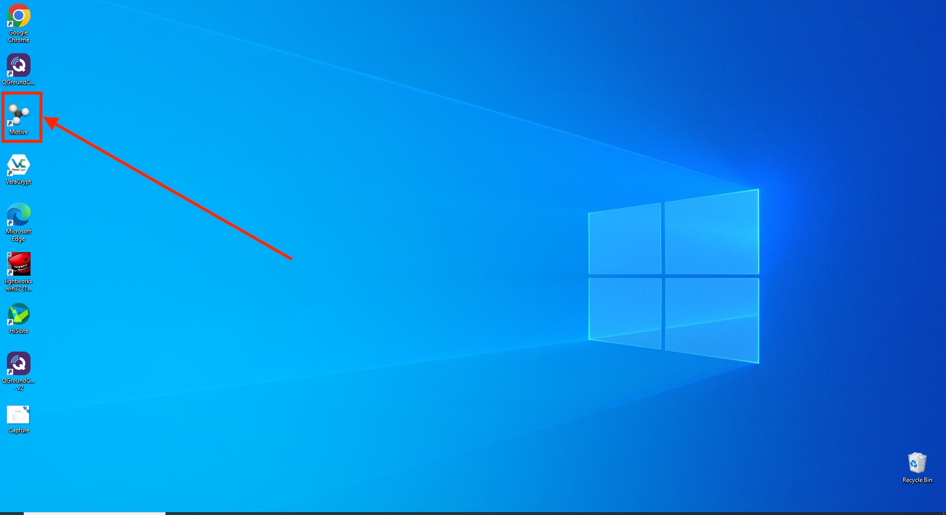
Launch the Motive application from the Windows desktop.
Open the Camera Calibration pane
 and click on
 Clear Maskfollowed byMask Visibleto mask all the bright spots in the arena that can be mistakenly identified as passive markers.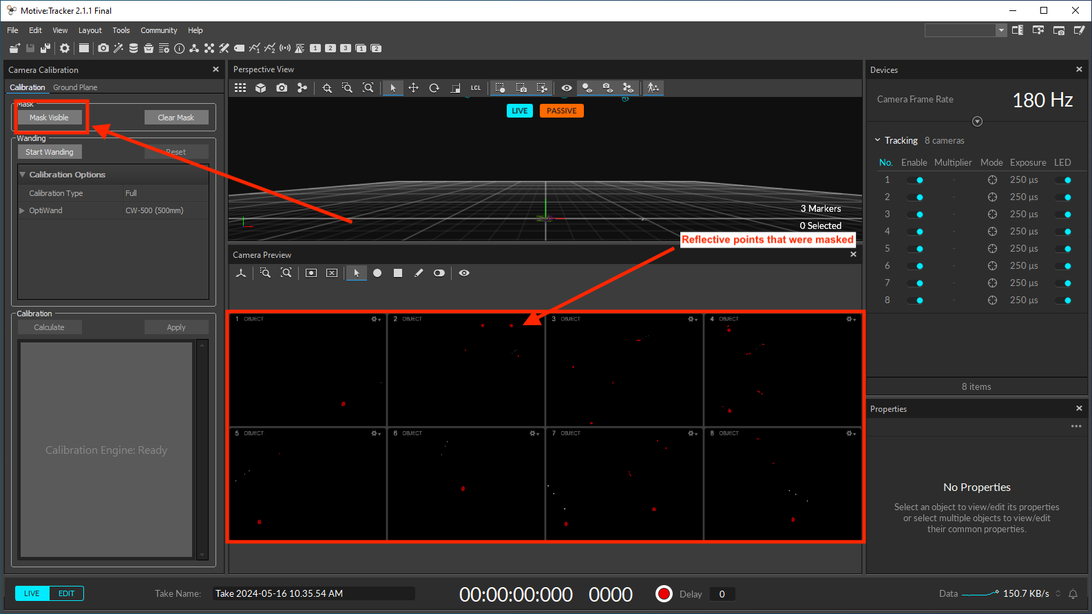
Start the calibration process by clicking on
Start Wanding.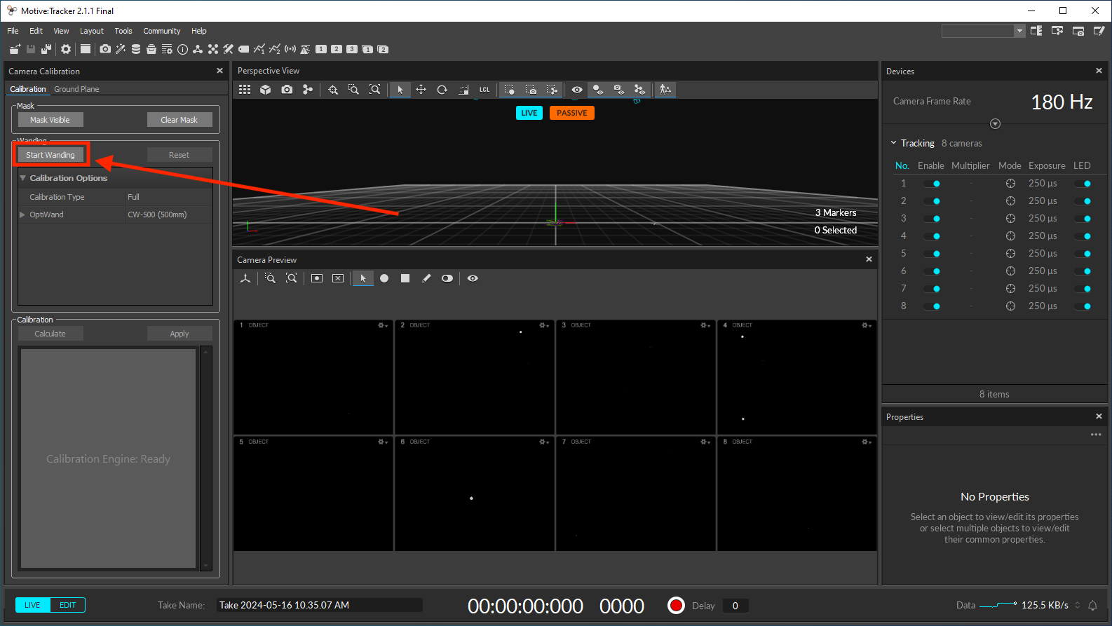
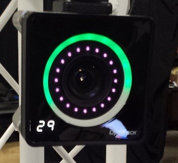
Enter the arena with the calibration wand in hand and wave it around the arena. Make sure that the LED indicator ring of all cameras is completely filled in green.
Click on
Calculatefollowed byApplyand wait for the Calibration Result Report window to pop up.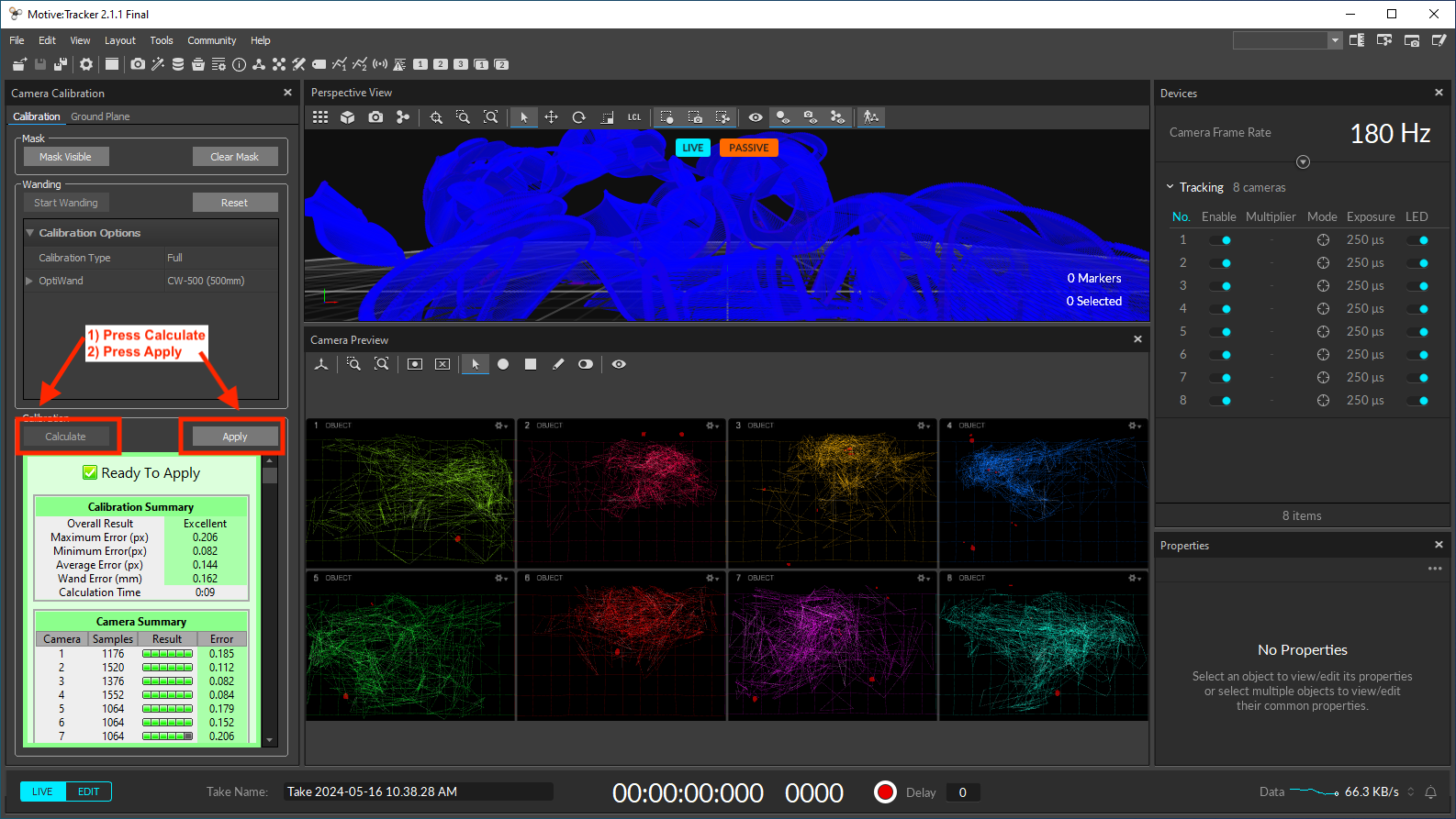
Check the Calibration Result Report. If it reports an Excellent or Exceptional calibration result, press
Apply. Else, pressCanceland repeat the wanding process.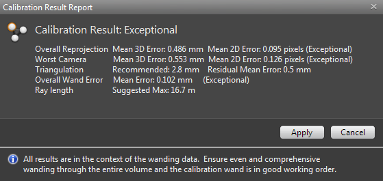
Place the calibration square in the center of the arena, with the shorter leg pointing towards the windows.
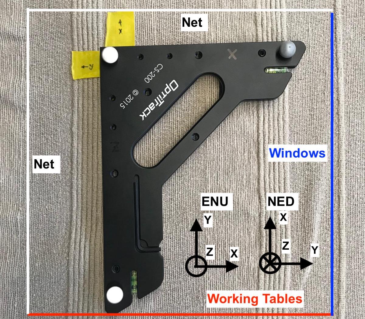
Have in mind that the motion data captured from the MCS is expressed in an East North Up (ENU) inertial frame, which is the standard in the ROS representation. The mavlink interface converts this data to a North East Down (NED) inertial frame with the attitude following the Front Right Down (FRD) of the rigid body.
Open the Ground Plane tab of the Camera Calibration pane and click on
Set Ground Planeto finish the calibration process.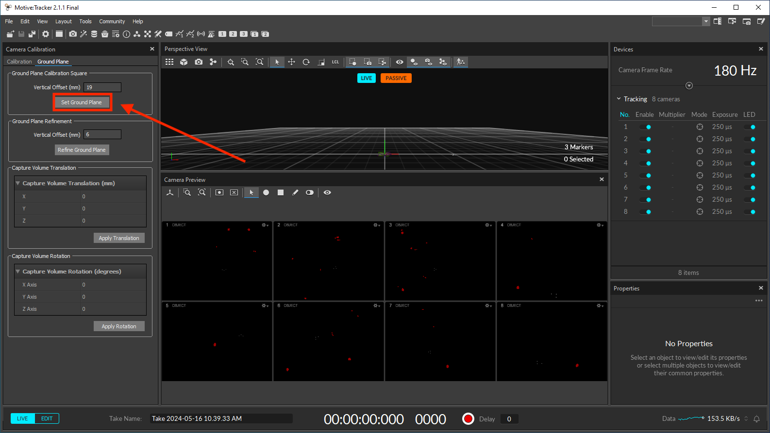
You can save your calibration file for later use. It can be used during multiple consective days of experiments in the arena. However, the calibration accuracy naturally deteriorates over time due to ambient factors, such as fluctuations in temperature. You should re-calibrate the MCS on a weekly basis.
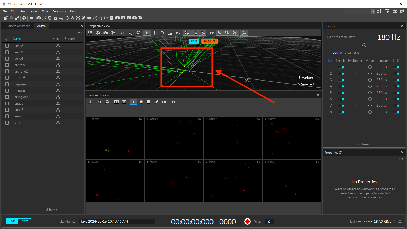
Take the calibration square out of the arena and place your vehicle inside the arena with its front pointing towards the windows. Select the group of markers you see on screen at once and check if all the markers placed on your vehicle are detected.
Create a rigid body from the selected markers by right-clicking over them and choosing the
Rigid Bodyfollowed byCreate From Selected Markers. On the Assets pane , you should see the newly created rigid body.
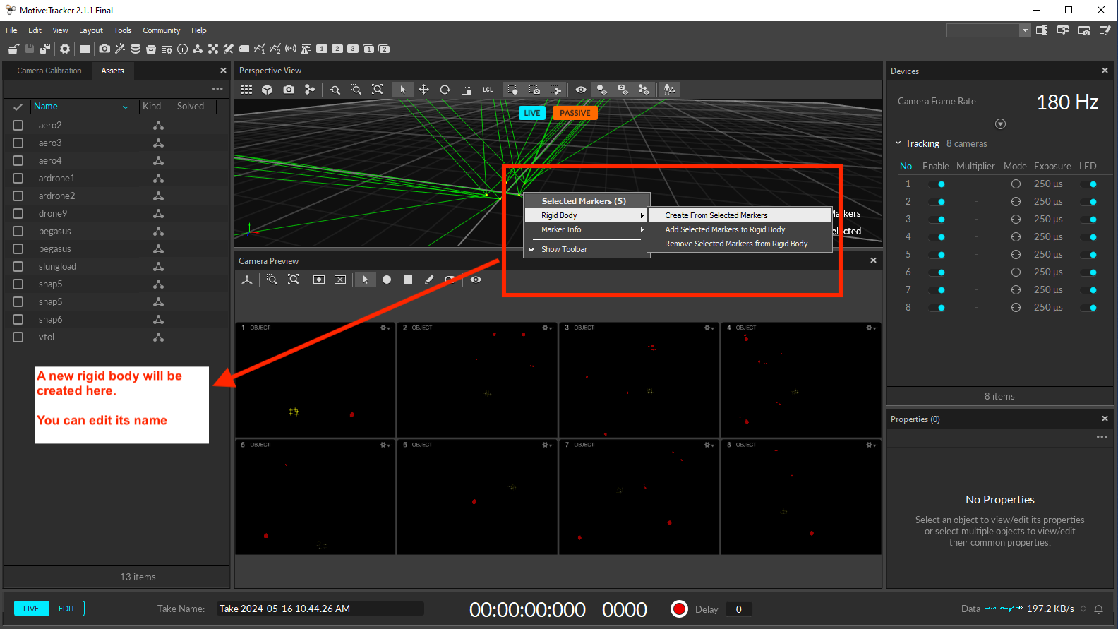
Troubleshooting
Here we provide some insight to solve some of the most frequent issues. Please check the Motive reference page for more information on the calibration and troubleshooting procedures.
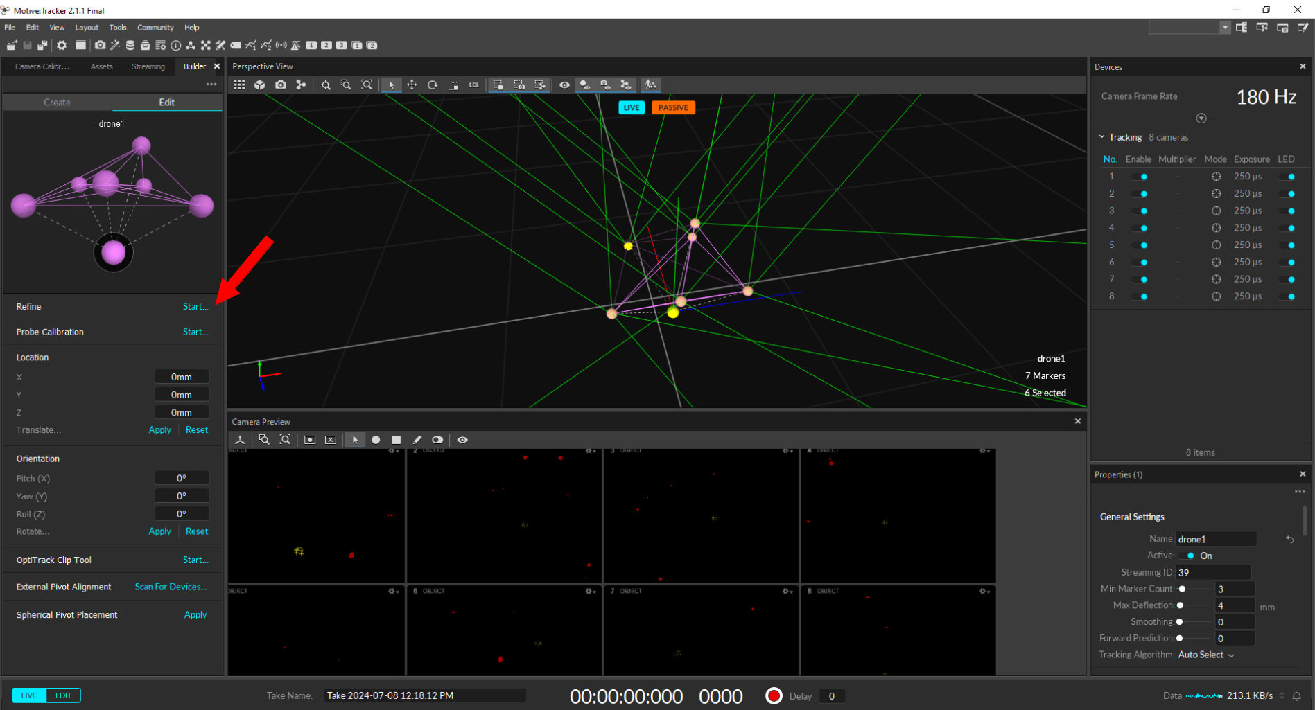
Shaky Rigid Body Asset
If by looking at an asset in the 3D viewport you notice that it is shaking when the Rigid body is stationary, you should then resort to the Rigid Body refinement tool to improve the accuracy of the Rigid Body calculations in Motive. This tool allows Motive to collect additional samples, achieving more accurate tracking results by improving the calculation of expected marker locations of the Rigid Body as well as the position and orientation of the Rigid Body itself.
From the View menu, open the Builder pane, or click the
 button on the toolbar.
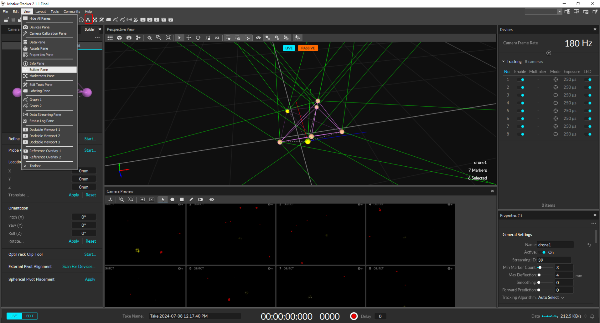
Click the Edit tab.
Select the Rigid Body to be refined in the Assets pane.
Place the Rigid Body in the center of the arena so as many cameras as possible can clearly capture its markers.
In the Refine section of the Edit tab of the Builder pane, click Start…
Slowly rotate the Rigid Body to collect samples at different orientations until the progress bar is full.
Marker Placement
Placing too many markers on one Rigid Body is not recommended. When too many markers are placed in close vicinity, markers may overlap on the camera view, and Motive may not resolve individual reflections. This can increase the likelihood of label-swaps during capture.
Whenever possible, though, it is best to use 4 or more markers to create a Rigid Body. Additional markers provide more 3D coordinates for computing positions and orientations of a rigid body, making overall tracking more stable and less vulnerable to marker occlusions.
Placing the markers in symmetrical shapes such as squares, isosceles, or equilateral triangles make asset identification difficult and may cause the Rigid Body assets to flip during capture. Within a Rigid Body asset, the markers should be placed asymmetrically because this provides a clear distinction of orientations.
Not having unique Rigid Bodies could lead to labeling errors especially when tracking several assets with similar size and shape. When tracking multiple objects using passive markers, it is beneficial to create unique Rigid Body assets in Motive. Specifically, you need to place retroreflective markers in a distinctive arrangement between each object, which will allow Motive to more clearly identify the markers on each Rigid Body throughout capture.